Hazardous Gas Extraction Booth Controller
· Standard · Custom [VFD Options]
Please click on the You Tube™ Link below to watch a short video on the Line Supervisory Control and Monitoring System.
♦ Extraction Booth Controller Demo
Extraction Booth Controller with Modbus RTU Communication.
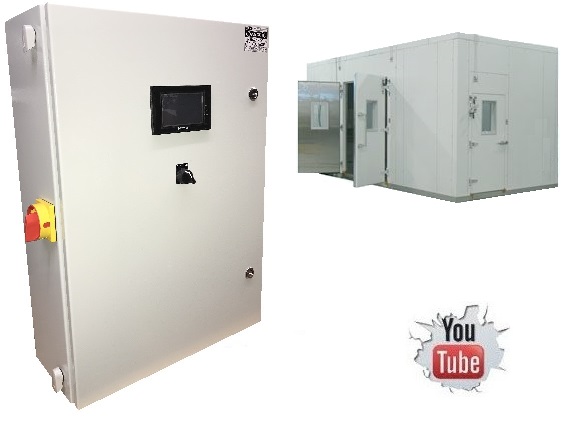
EXTRACTION BOOTH CONTROL PANELS
Our Extraction Booth Control Controller is designed to control fan motors from a M2A gas sensors with variable speed drives to offer reliable, economic, automatic control with a number of user friendly features.
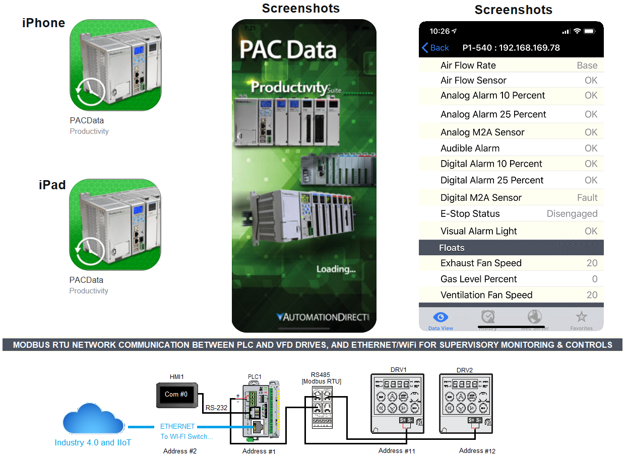
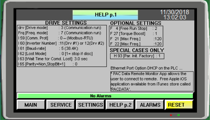
New free Apple iOS application available from iTunes store called 'PACDATA', PAC Data Remote Monitor App allows the user to connect to remote PAC systems from a Wi-Fi, or cellular network connection. The Remote user can monitor the local PAC system and user tags configured for remote access inside the tag database of the AutomationDirect Productivity 1000 CPU.
Go Green Energy Use
• VFDs reduce energy demands and save on operating costs.• VFDs efficiently control motors to exhaust harmful gases.
208-240 Vac, 1/3 Phase, 50/60 Hz.
PM1M-004400UL
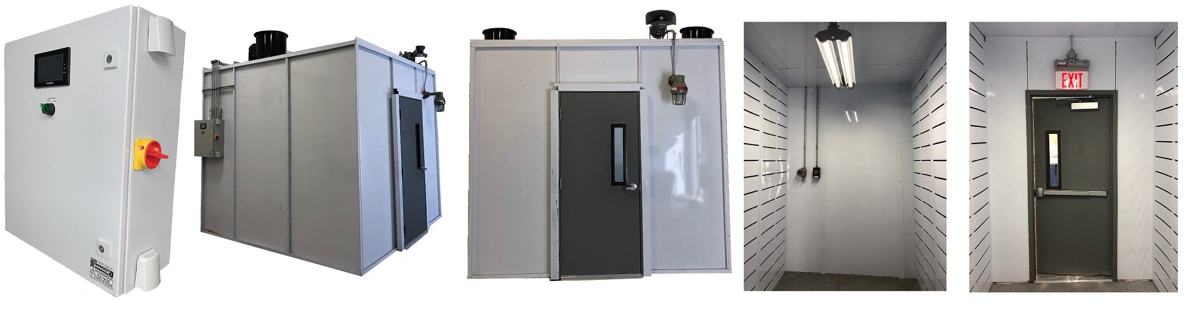
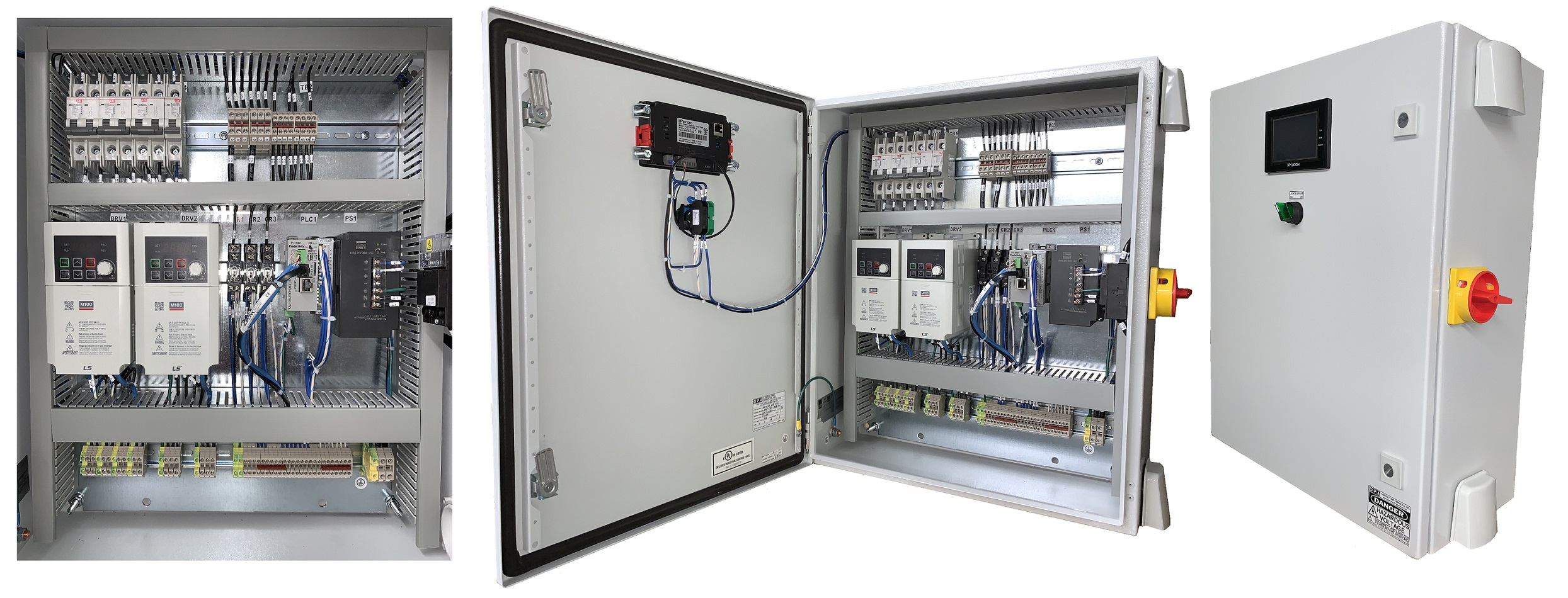
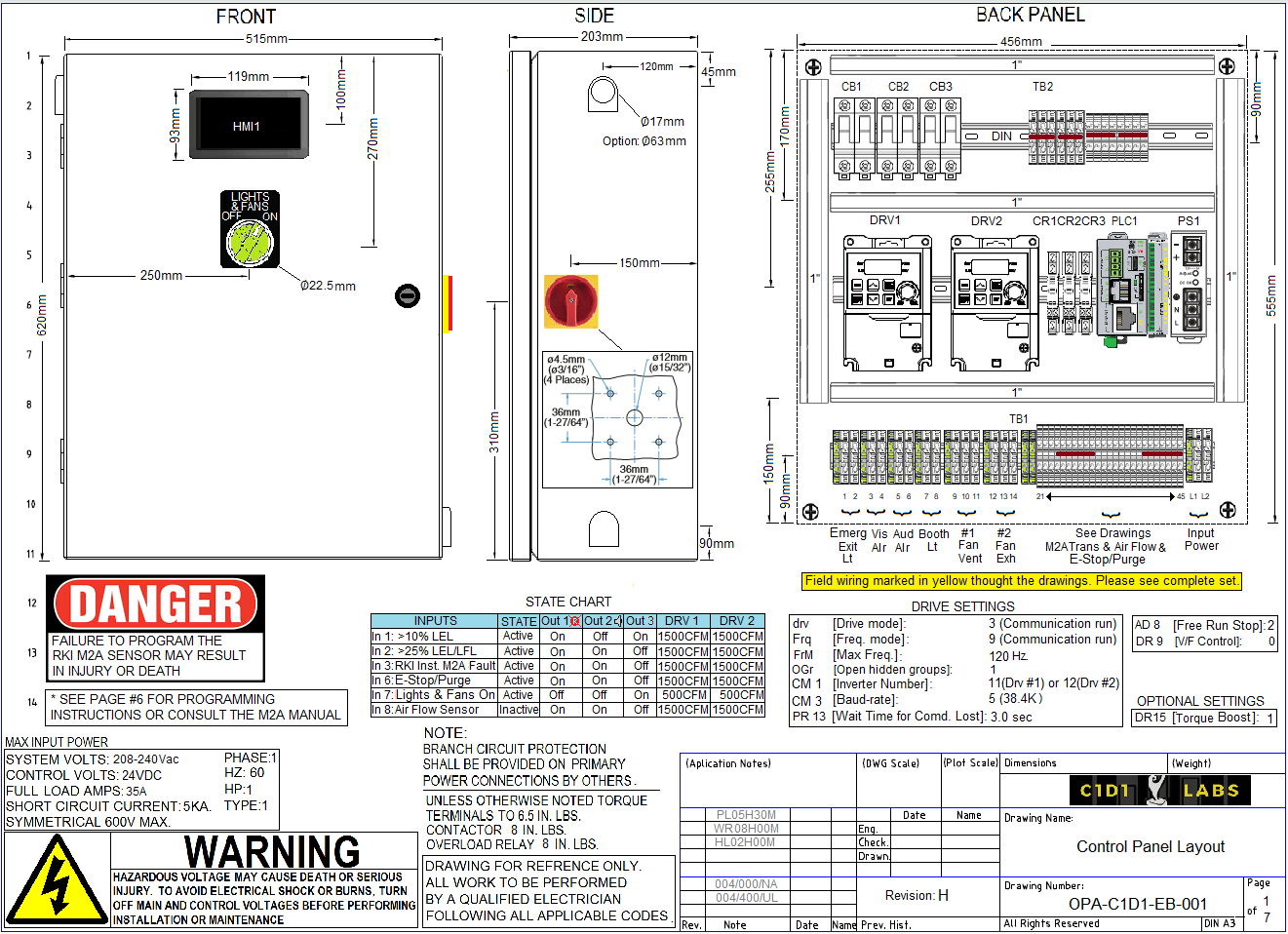
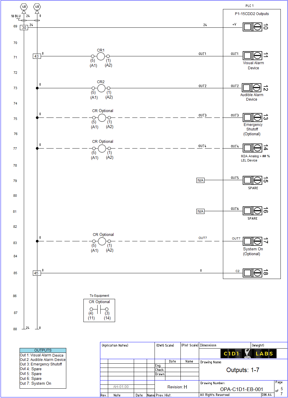
Panel Drawing ... Use the Right Click on your mouse and select Save Picture As... to Copy it to your PC for better viewing.
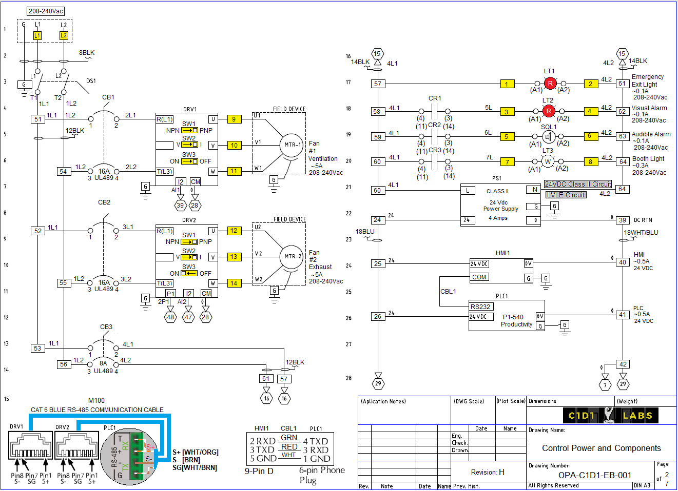
Panel Drawing ... Use the Right Click on your mouse and select Save Picture As... to Copy it to your PC for better viewing.
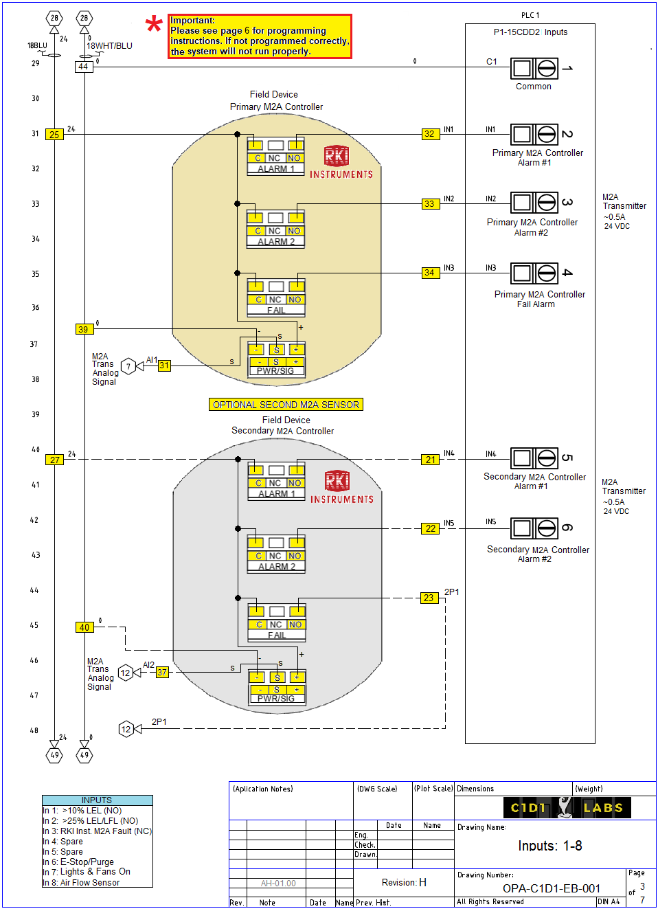
Panel Drawing ... Use the Right Click on your mouse and select Save Picture As... to Copy it to your PC for better viewing.
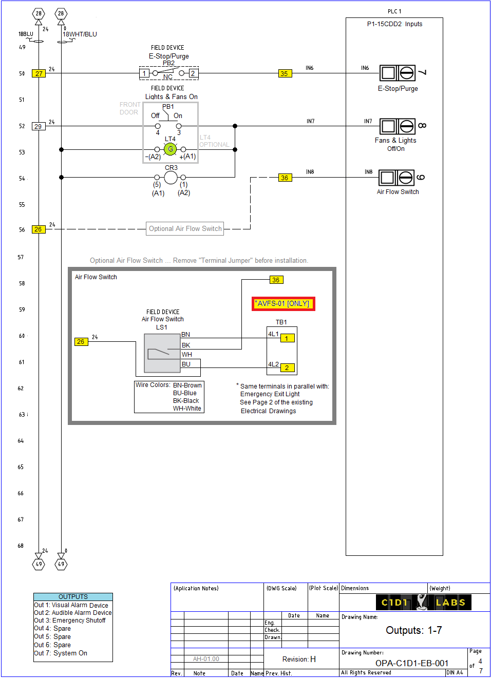
Panel Drawing ... Use the Right Click on your mouse and select Save Picture As... to Copy it to your PC for better viewing.
Panel Drawing ... Use the Right Click on your mouse and select Save Picture As... to Copy it to your PC for better viewing.
Panel Drawing ... Use the Right Click on your mouse and select Save Picture As... to Copy it to your PC for better viewing.
Panel Drawing ... Use the Right Click on your mouse and select Save Picture As... to Copy it to your PC for better viewing.
Panel Drawing ... Use the Right Click on your mouse and select Save Picture As... to Copy it to your PC for better viewing.
• 22mm Industrial Strength Two-Position Selector Switches.• Easy to use Two Button Controls.
• PLC for internal logic control.
• VFD for fan motor controls.
• Low-voltage control[24Vdc].
• NEMA Enclosure.
• UL 508A Listed [Optional].
• Built at our facility in North Carolina, USA by a NON UNION SHOP.
PRICE: Please call M1M at (336)394-4791 or send us an E-Mail.
Authorized Sales Distributor:Merchant1Manufacturing
EXTRACTION BOOTH CONTROLLER HMI SCREEN DESCRIPTIONS
The following pictures will describe in general the operation of the control system.
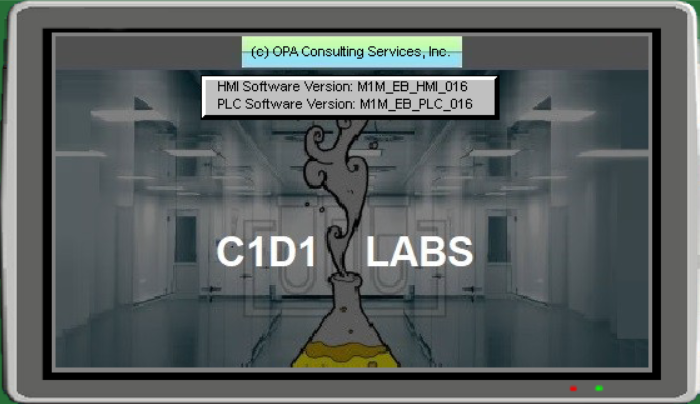
Startup Screen
This is the first screen that appears when power is turned on. It displays the software version of the PLC (Programmable Logic Controller) and the HMI (Human-Machine Interface), and it only last seconds.
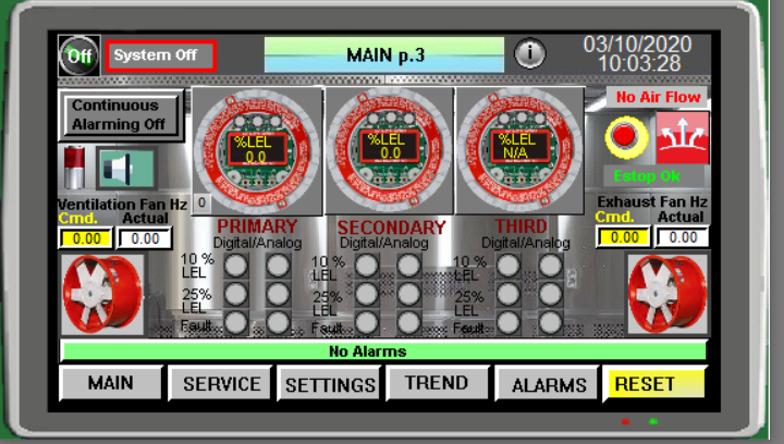
Main Menu Page 1-3
This screen is the home/default process monitoring screen when the system is running. This screen displays the fans running status by turning green from a red stop. The command speed is the speed set from Basic and Purge set points that are located in the SETUP p.1 screen to be described later. It also has an alarm bar at the bottom, displaying the alarms as they happen. The screen changing buttons ate at the very bottom of this screen.
In the middle of the screen you will see a picture of the M2A Gas sensor. The system is designed to take the digital/discrete and also analog signals to make it a robust failsafe system. The discrete signals shall be programmed in the sensor itself and the analog are pre programmed in the PLC. They are changeable and must be calibrated to make sure that they meet the customer’s requirements. These are located on the SETUP screens.
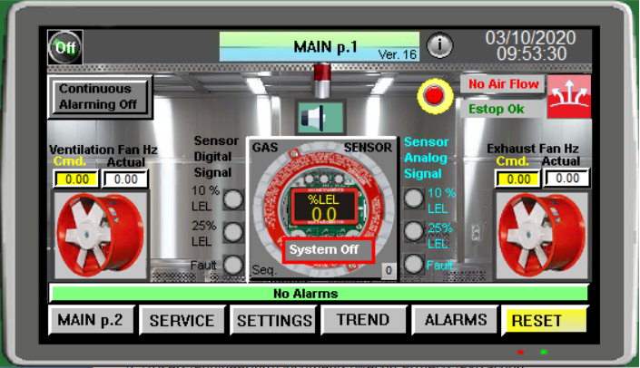
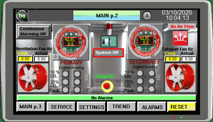
The "Continuous Alarmig Off/On" enable the M2A Gas Sensor to be active and alarm while the lights and fans are in the Off position, basically in a nut shell, continuos Gas monitoring.
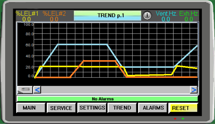
Trend Menu
This Real Time Trend Screen displays the fan motors speed in Hz and M2A sensor analog gas level output in percent.
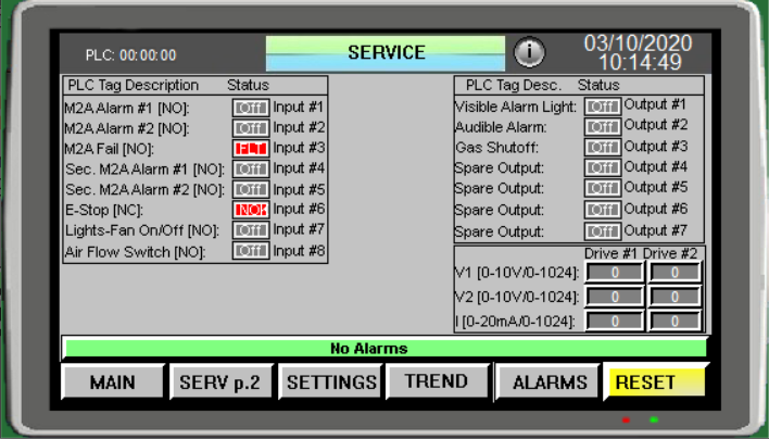
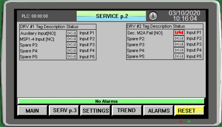
Service Page 1-2
This SERVICE page is intended for an electrical technician. It is intended for debugging the system, in case of a component/s were to go bad.
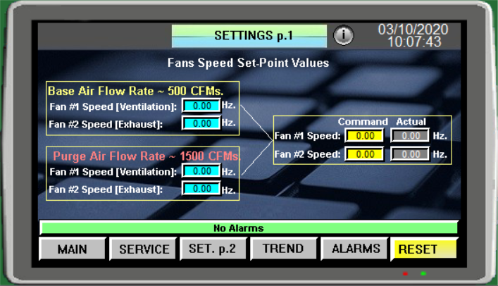
Setup Page 1
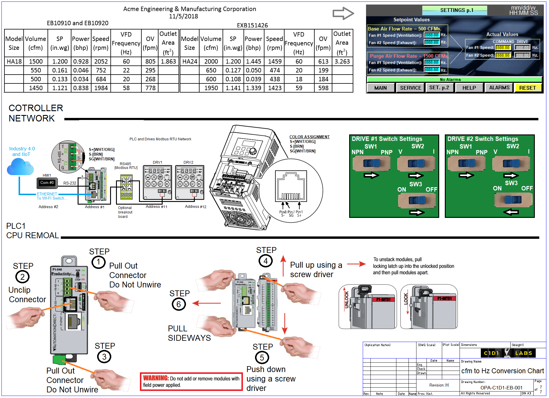
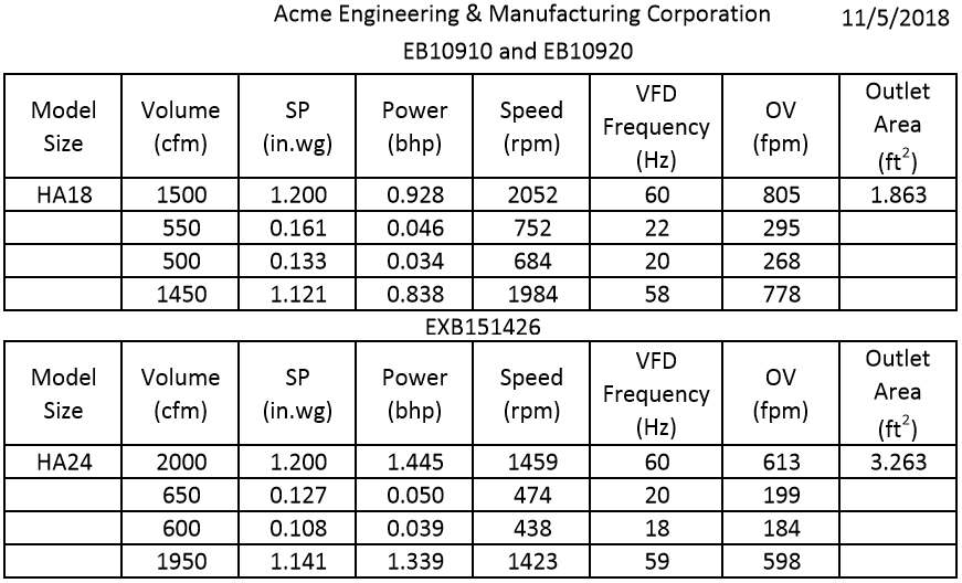
The SETUP page 1 is where one enters the drive speed settings in hertz. One must look on the fan manufacturer specifications sheet or chart to determine the proper speed settings that correspond to CFMs. Also an Air Flow Rate sensor is highly recommended to measure the fan CFMs to confirm the theoretical results.
Setup Page 2
The most important part of the SETUP page 2 is the values for the M2A sensor. The 10% and the 25% are entered respectively. These values serve a backup to the digital settings in the M2A sensor. If for some reason the digital signals from the M2A sensor are inoperable or disconnected these settings will activate the proper alarms.
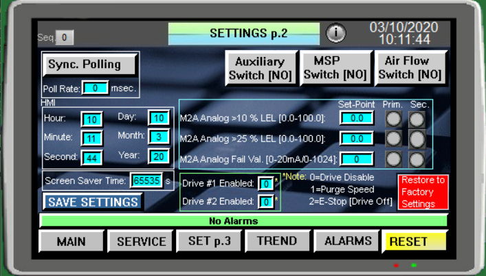
The Drive # 1 Enable and Drive #2 Enable has multiple scenarios associated with the way the two fans operate. One example is by placing a 0 in either one or both will disable the drive/fan. Not recommended unless unique solution is necessary.
The second and the default scenario which defaults to "1" in both fields, allows the E=Stop Button to be used as a System Purge when activated.
The third option is by placing "2" in both fields, this allows the E=Stop button to turn "Off" all the fans, audible and visual alarms, when activated.
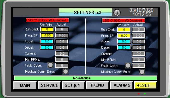
Setup Page 3
This screen is somewhat self explanatory. It displays the fan motor operating parameters. You can change the Acceleration and Deceleration speeds from here.
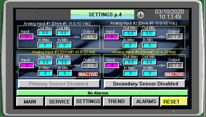
Setup Page 4
The SETUP page 3 is where the value for the M2A sensor is scaled. The raw analog value in Analog Input # 3[Drive #1AI] equation is transformed to a percent value for alarming and monitoring. A linear equation [y=mx + b] is used to calculate the engineering units. The scale value is entered in the Out Max (100%) and Out Min (0%). The In Max (1015) which corresponds to 20mA and In Min (201) which corresponds to 4mA is a 12 bit analog to digital converter located in the Frequency Drive.
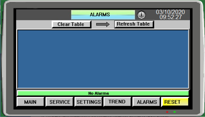
Alarm Page 1
The ALARM screen displays the active and most recent alarm history. Use the scroll keys on the side of the table to scroll up and down to view the previous and current alarms and the top two keys to clear and refresh the alarm table.
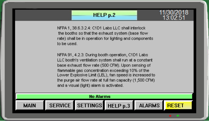
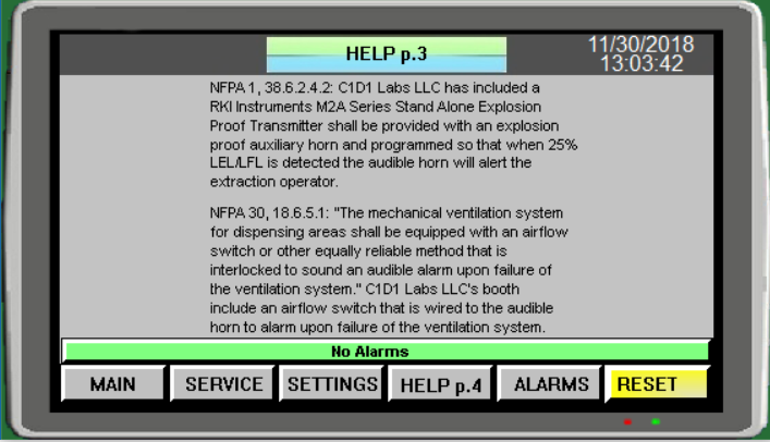
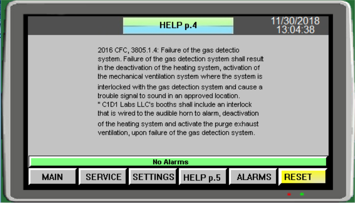
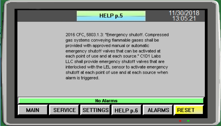
Help Page 1-6
These following screens contain information about the Frequency Drives and the theory of operation of this controller.
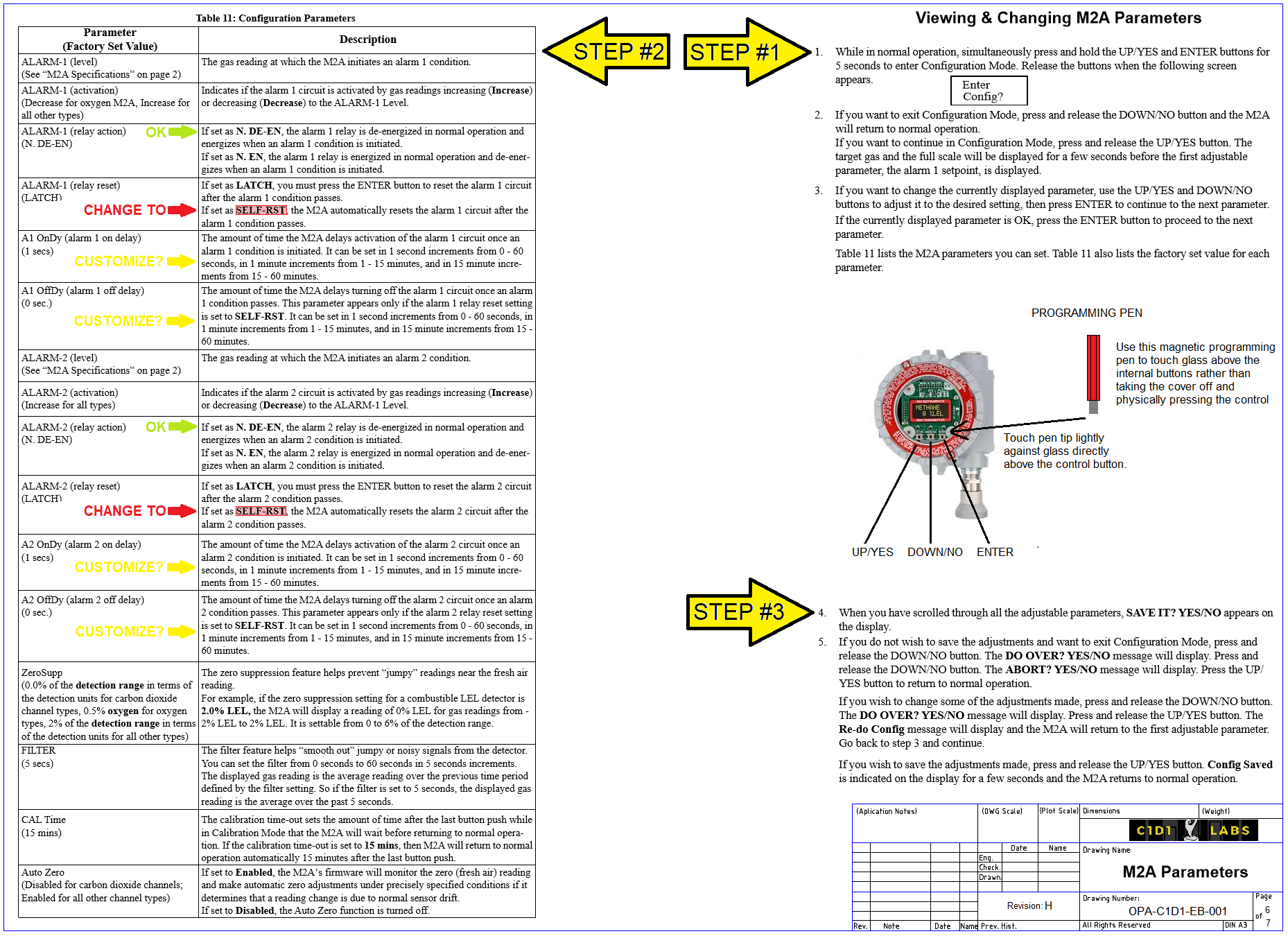
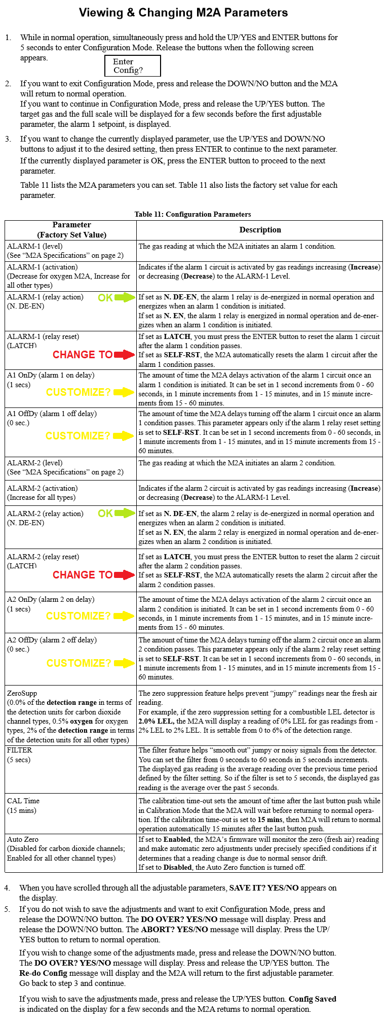
M2A Transmitter Settings
The M2A Transmitter must be programmed to the following settings in the table below in order to properly work with our controller.
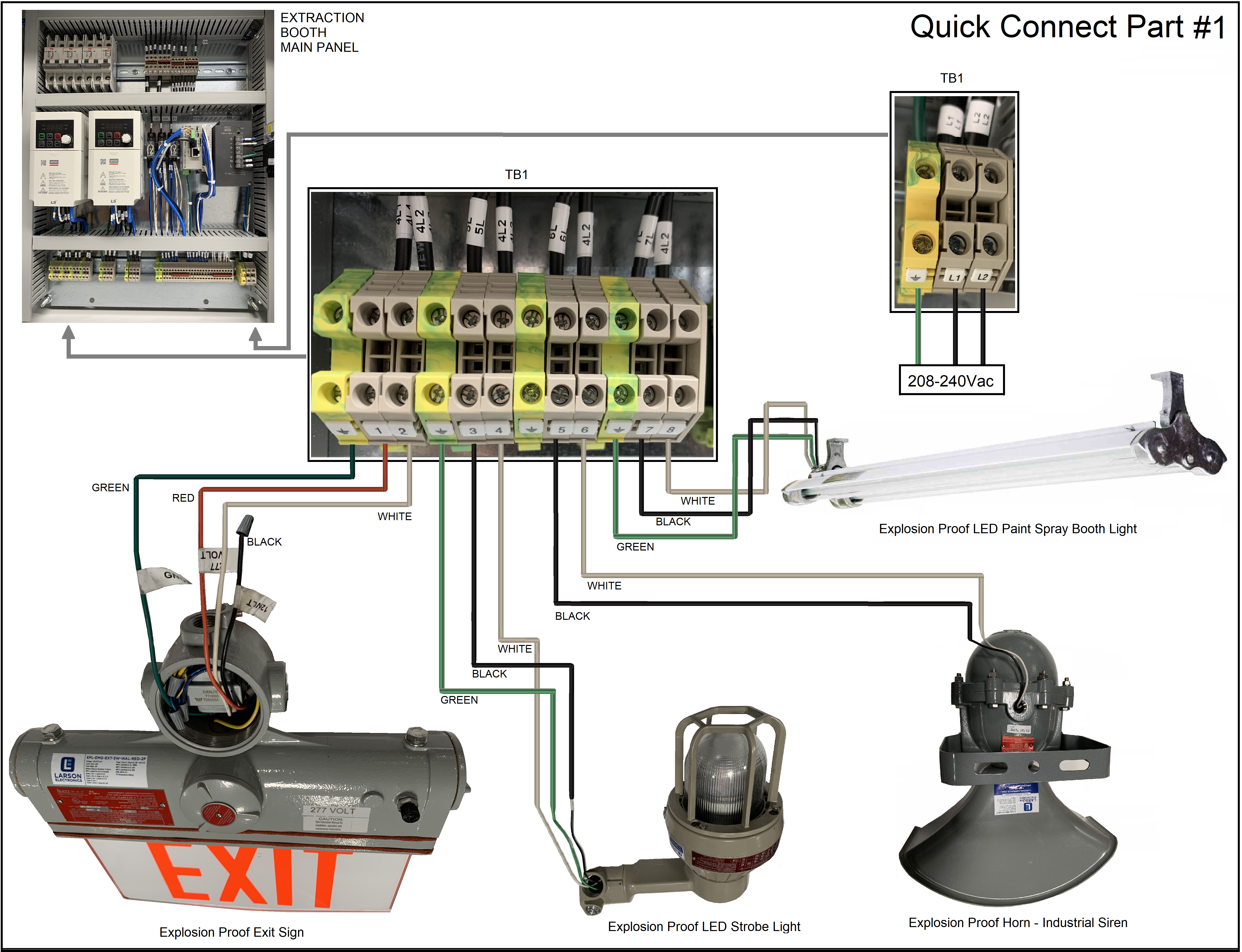
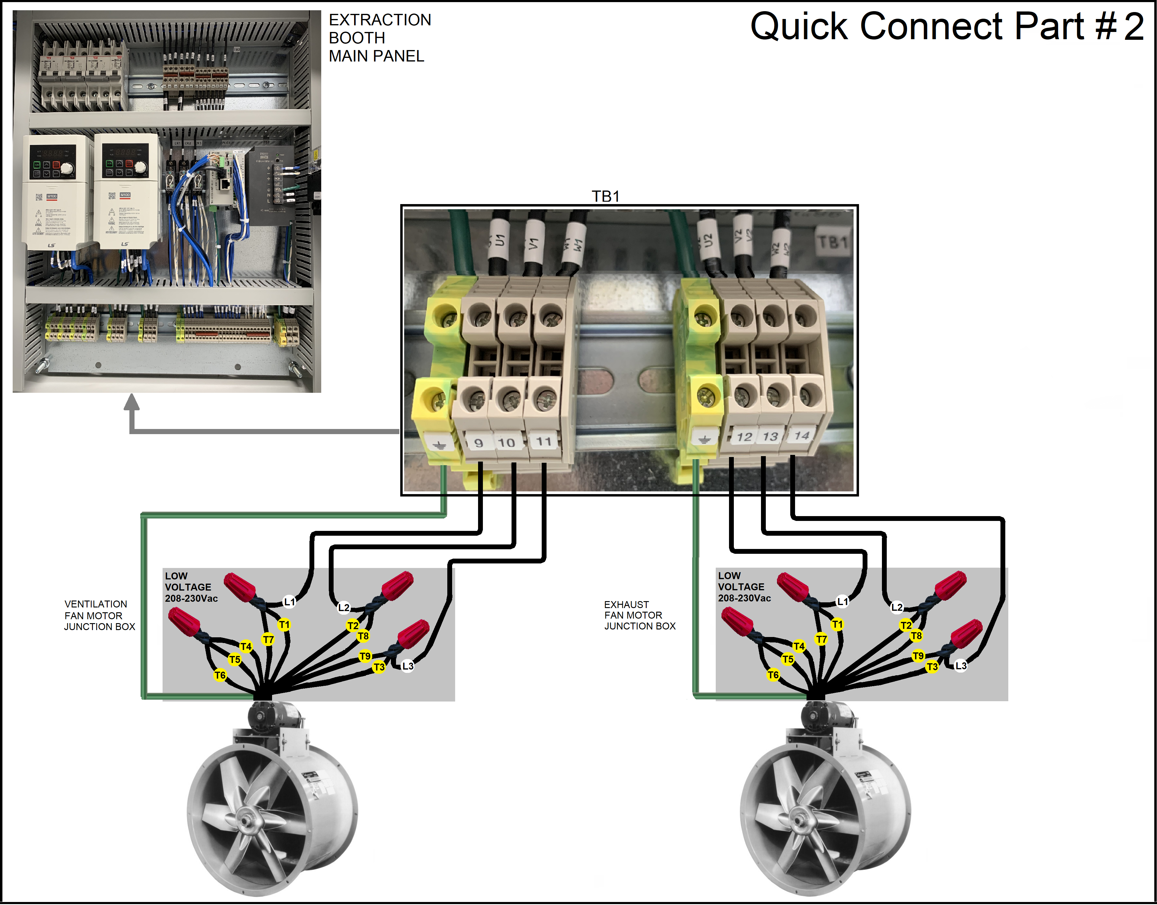
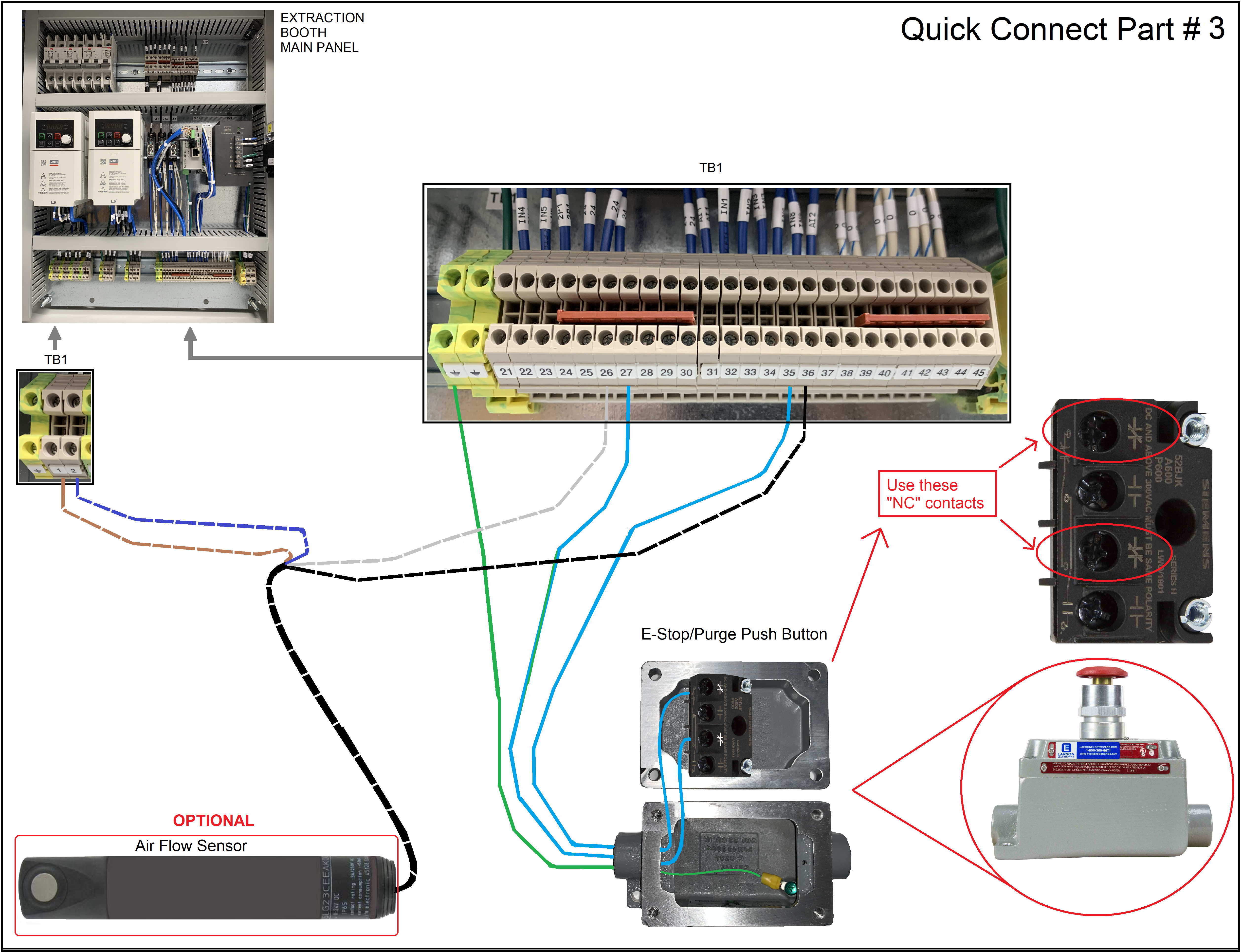
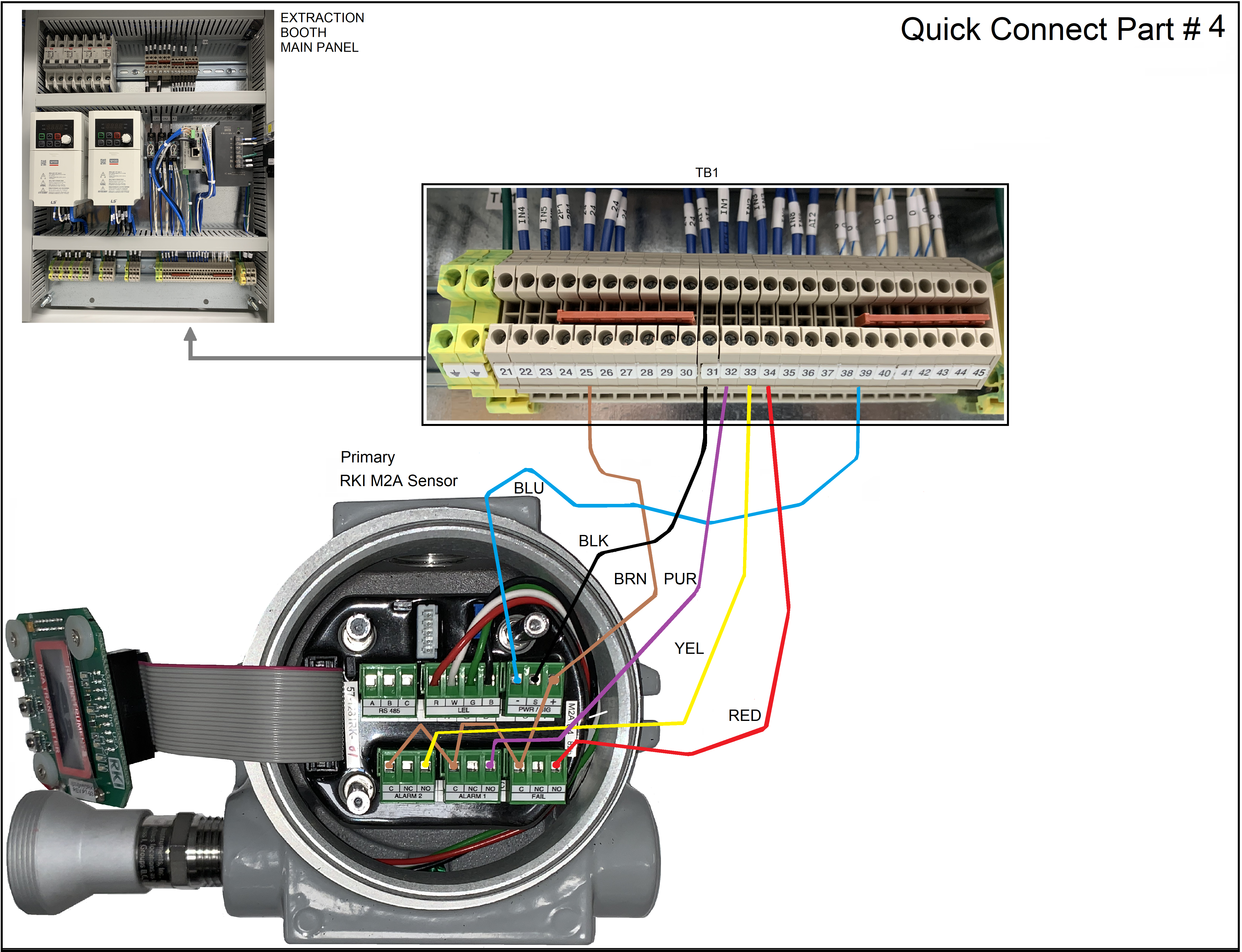
Quick connect graphical representation options ...
Non technical representation of the electrical connections.
Panel Drawing ... Use the Right Click on your mouse and select Save Picture As... to Copy it to your PC for better viewing.
Panel Drawing ... Use the Right Click on your mouse and select Save Picture As... to Copy it to your PC for better viewing.
Panel Drawing ... Use the Right Click on your mouse and select Save Picture As... to Copy it to your PC for better viewing.
Panel Drawing ... Use the Right Click on your mouse and select Save Picture As... to Copy it to your PC for better viewing.

Panel Drawing ... Use the Right Click on your mouse and select Save Picture As... to Copy it to your PC for better viewing.
© Copyright 2009 OPA Consulting Services, Inc.
Designed by: OPA Consulting Services, Inc.
Links to our Partners:
4419 Hunter Oaks Ct.
High Point, NC 27265 USA